2019年11月1日星期五

Pancake Stepper Motor: Bipolar, 200 Steps Overview

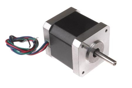
This pancake bipolar stepping motor from Sanyo has a 1.8° step angle (200 steps/revolution). Each phase draws 1 A at 4.5 V, allowing for a holding torque of 1 kg-cm (14 oz-in). The motor has four color-coded wires terminated with bare leads: red and yellow connect to one coil; orange and blue connect to the other. It can be controlled by a pair of suitable H-bridges (one for each coil), but we recommend using a bipolar stepper motor driver or one of our Tic Stepper Motor Controllers. In particular, the Tics make control easy because they support six different interfaces (USB, TTL serial, I²C, RC, analog voltages, and quadrature encoder) and are configurable over USB with our free configuration utility.

Our 5 mm universal mounting hub can be used to mount objects on the stepper motor’s 5 mm-diameter output shaft.

Specifications
Size: 50 mm square × 11 mm, not including the shaft
Weight: 90 g (3.2 oz)
Shaft diameter: 5 mm
Steps per revolution: 200
Current rating: 1 A per coil
Voltage rating: 4.5 V
Resistance: 4.5 Ω per coil
Holding torque: 1 kg-cm (14 oz-in)
Inductance: 2 mH per coil
Lead length: 30 cm (12″)
Output shaft supported by two ball bearings
More specifications are available in the datasheet (352k pdf).

Dimensions
The following diagram shows the stepper motor dimensions in mm. The dimension labeled “L” is 11 mm. Though the dimension diagram below shows output shafts on both sides, this stepper motor only has a single output shaft (on the side with the mounting plate) with a length of 5 mm and a diameter of 5 mm. This shaft works with our 5 mm universal mounting hub.

Pancake Stepper Motor: Bipolar, 200 Steps Overview


https://forum.arduino.cc/index.php?topic=339184.120
https://oyostepper520.seesaa.net/article/471258859.html?1572515035

2018年12月13日星期四

Analysis of a Hybrid Step Motor - Part One

Hybrid stepper motors wholesale are used as actuators for equipment where position detection accuracy is required, such as the joints of robots or rotary tables for machine tools. The rotor has a construction that sandwiches a magnet that is magnetized in the axial direction between two rotor cores that have serrated teeth to create salient poles, and the tips of the stator core’s teeth are shaped like gears as well. Because the rotation resolution is determined by the number of rotor teeth and the number of phases for the drive coil, the design uses large number of teeth, such as 50 or 100, so the angle resolution can be increased .The most important characteristics for a stepper motor are the controllability, the detent torque, which is a non-excitation holding torque, and the stiffness torque, which is an excitation holding torque, and not the motor’s output.


The two-plated rotor core of a stepper motor has an N pole on one side and an S pole on the other, so a multipole magnet is achieved by deviating the saliency of the gear condition by 1/2 pitch. Consequently, the magnetic circuit is 3D. There are also times when the division pitch geometry of the teeth is complicated, so it is necessary to carry out a 3D electromagnetic field analysis using the finite element method (FEM) to proceed with an accurate preliminary study.


This document introduces how the detent torque and stiffness torque can be calculated for a hybrid nema 34 stepper motor.


The detent torque is shown in fig. 1, and the magnetic flux distribution in the XY-plane at the rotation position of 0.45 degrees is shown in fig. 2. A closer view to show the flux distribution in the gap is shown in fig. 3. These results reveal that the flux in both the rotor and stator is saturated even with no excitation. The flux leakage around the tips of the teeth, due to saturation, can be expected to have a large effect on the detent torque.


Fig. 4 shows the stiffness torque with one-phase excited and fig. 5 shows the stiffness torque with two-phase excited. The flux distribution in the gap of the XY-plane with one-phase excited is shown in fig. 6, and the flux distribution in the gap of the XY-plane with two-phase excited is shown in fig. 7. As with the detent torque, the magnetic flux around the teeth is saturated. The flux leakage caused by the saturation can be expected to also have a large effect on the stiffness torque.

What’s the difference between detent torque and holding torque?


2018年12月8日星期六

How to set a stepping motor’s current limit

 Stepper-motor current limiting serves a few functions. Stepper-motor overcurrent can cause overheating as detailed in FAQ: Aren’t heat and noise common stepper motor problems? At its most extreme, overcurrent can cause rotor demagnetization. Recall that current effects acceleration — as in FAQ: What are the requirements for stepper motor acceleration? So any design that uses microstepping needs current limiting, as different windings require different current levels.

Options for current limiting abound. The simplest to use a resistor. This option is easy to implement but has drawbacks. It causes significant heating and (because factors such as motor inductance change with rotor position and frequently go undocumented) can be difficult to implement.


Another option — linear motor current limiters — employ a pair of power resistors. They offer better performance than simple limiters using a single resistor. Instead of limiting current linearly as resistor circuits, they limit current asymptotically … and usually the limit is far above a motor’s rated current. Both types of current limiters are automatic. However, they generate heat.

Still other methods exist to set current limit as part of open-loop systems.

One is to use a voltage boost at the beginning of startup. The controller delivers almost the entire supply voltage early. At the target current, the voltage drops down to only what’s necessary to maintain target current. Use of a dual-voltage supply is also possible. Here the drive applies high voltage until the current reaches the target level, then it switches to operating voltage and the high voltage switches off.

One caveat: This scheme can pose a problem if the drive applies the high voltage applies too long — as that can risk of burning out the motor or demagnetizing it. If the design uses software control to run this circuit and the programmer is unfamiliar with the application, the software may not prevent this situation.

Pulse-width modulation or chopping is another option. Here as current increases, the controller holds supply input to 100% duty cycle.

At target current, duty cycle drops to whatever is necessary to maintain operation. While effective, this method’s drawback is torque ripple. This can cause high-pitched noise in smaller motors. In larger motors, this can create ac voltages on nearby lines. To reduce ripple, designs will often increase the chopper frequency … but this can only go so far before losses are excessively high.

BASICS OF STEPPER MOTORS YOU SHOLD KNOW

2018年12月5日星期三

Stepper Motor Driver Circuit You Shold Know

Technically stepper motor driver circuit is a Decade Binary Counter circuit. The advantage of this circuit is, it can be used to drive stepper motors having 2-10 steps. Before going any further let’s discuss more about the basics of stepper motor.

Stepper Motor Image
The name of this motor is given so because the rotation of shaft is in step form which is different from DC or any other motor. In other motors the speed of rotation, the stop angle are not in complete control unless necessary circuit is inserted. This non-control is present because moment of inertia, which is simply a character to start and stop on command without delay. Consider a DC motor, once its powered the speed of motor increases slowly until it catches the rated speed.

The step motor hybrid does not work on constant supply. It can only be worked on controlled and ordered power pulses. Before going any further we need to talk about UNIPOLAR and BIPOLAR stepper motorS. As shown in figure in a UNIPOLAR stepper motor we can take the center tapping of both the phase windings for a common ground or for a common power. In first case we can take black and white for a common ground or power. In case 2 black is take for a common. In case3 orange black red yellow all come together for a common ground or power.

Unipolar stepper motor

In BIPOLAR stepper motor we have phase ends and no center taps and so we will have only four terminals. The driving of this type of stepper motor is different and complex and also the driving circuit cannot be easily designed without a microcontroller.

The circuit which we designed here can only be used for stepper motors of UNIPOLAR type.

The power pulsing of UNIPOLAR stepper motor wholesale price will be discussed in circuit explanation.


Circuit Components
+9 to +12 supply voltage
555 IC
1KΩ, 2K2Ω resistors
220KΩ pot or variable resistor
1µF capacitor, 100µF capacitor (not a compulsory, connected in parallel to power)
2N3904 or 2N2222 (no. of pieces depend on type of stepper if it’s a 2 stage we need 2 if it’s a four stage we need four)
1N4007 (no. of diodes is equal to no. of transistors)
CD4017 IC, .

Why do you use a stepper motor?

2018年11月24日星期六

Comparing closed-loop and open-loop stepper systems

Recently, I got the chance to work with Eric Rice and Jeff Kordick at OYOSTEPPER Products on a technical feature detailing new technologies making step motor systems even faster, quieter, and more energy-efficient than ever before.

Step motor systems have come a long way from the early days of voltage drives and full stepping. First came PWM drives and microstepping and then digital signal processors (DSPs) and anti-resonance algorithms. Now, closed-loop stepper designs could become the new cornerstone of the motion control industry. One such closed-loop system implements on an integrated motor design that includes a feedback device, driver and controller boards, power, communication and I/O electronics, and system connectors on the motor’s side and back.

Consider how open-loop stepper systems are simple beasts. One simply sets the drive for the motor’s rated current and the drive will do its best to supply that current to the motor at all times, whether the resulting torque is needed or not. This often causes the generation of heat instead of energy towards the application function — and is the reason why open-loop stepper systems typically run hotter than closed-loop counterparts .


Above is a Relative Comparison Chart for StepSERVO closed-loop systems versus open-loop systems. Note the superior performance of the closed-loop stepper motor system as demonstrated in the results of laboratory testing that compare two systems for acceleration (torque), efficiency (power consumption), position error (accuracy), heat generation, and noise levels.


2018年11月20日星期二

Why to Buy Stepper Drives and Controls at OYOSTEPPER

A stepper motor is an electrically powered motor. Current is passed to the drive shaft, which then rotates in small step-like motions. Stepper motors do not rotate smoothly or continuously. They are designed to power digital devices, which require precise and tightly-controlled motor movements with no feedback. Items containing stepper motors include cars, computers, toys, robotic arms, printers, and robotic model kits.

When purchasing stepper motor drivers, also called controllers, several factors must be taken into consideration. Buyers should make sure that the motor is compatible with the driver, as there are several different types. The number of wires in the motor determines whether a bipolar or unipolar driver is required. Maximum current input and output of the motor also impact which driver to purchase, as do features such as step modes, step frequency, and protection circuitry.

Why to Buy Stepper Drives and Controls at OYOSTEPPER


Buying Stepper Drives and Controls on OYOSTEPEPR

OYOSTEPEPR has a large selection stepper drives and controls, available in both new and used condition, and the price range varies significantly across the range. Buyers should use specific search terms to get the most appropriate results results, such as "micro stepper drive," "chopper drive," or "unipolar chopper drive." Buyers can search from the Business and Industrial, Consumer Electronics, and Computer, Tablets, and Networking portals, which also provide relevant search results.

Buyers can narrow their search results by choosing to view specific listing types, such as Buy It Now or auction format. Other result narrowing options include viewing only new or only used items, items within a specific price range, or only items from Top Rated Sellers.

Buyers should ensure the drive is in good working order, particularly if it is a secondhand unit.

Buyers should also ensure that the postage costs are acceptable, and should take note of the estimated delivery time. They should also determine whether the seller offers postal insurance for expensive items. Buyers are encouraged to contact sellers and ask any questions not covered in the item description.

Buyers should choose to buy from sellers who have large amounts of positive feedback, or sellers who possess a "Top Rated Seller" seal. A "Top Rated Seller" seal indicates that the seller has a sterling eBay reputation, and has provided many customers with quality products and great service.

Conclusion
To choose the correct analog stepper drivers or closed loop stepper driver
 buyers must consider their budget, the intended application of the stepper motor, and the required features. Buyers should ascertain which drives are compatible with the motor in question, since some motors will not work with an incorrect drive. The required features are also important considerations. For example, bi-level drives, while very stable and efficient, are not capable of performing micro stepping. This means that despite their reliability, these drives do not offer the same precision and resolution as a chopper drive. For those on a tight budget, secondhand drives in good working order are a good choice. This enables buyers to purchase a high end drive model at an affordable price.

2018年10月26日星期五

High Torque Nema 11 DC Stepper Motor NEMA 11 Frame Size 28 x 28mm 1.8°Step Angle

NEMA 11 Frame Size(28 x 28mm)
1.8° Step Angle
High Torque - Up to 17 oz-in
High Step Accuracy and Resolution
Low Vibration and Noise
DC Stepper Motor
Can be Customized for
-Winding Current
-Shaft Options
-Cables and Connectors
Typical Applications: Inject printers, Analytical and Medical Instruments, Textile Equipment, Embroidery Machine, Precision Telescope Positioning Systems, High Speed Dome Camera and Robotics
cnc stepper motor/step motor/stepper motor/NEMA 11 28 x 28mm stepping motor
NEMA 11 Frame Size 28 x 28mm 1.8°Step Angle


The 11HS Series DC Stepper Motor have bigger size than Nema 8HS DC Stepper Motor, but have much bigger torque than the latter. These DC Stepper Motor were designed to offer the highest possible torque while minimizing vibration and audible noise. Unlike DC motors, the 11HS series DC Stepper Motor already has a very high torque at low speed and often gears are not required which leads to considerably more economical drive solutions. The standard 4 lead wire DC Stepper Motor can be connected to allow the flexibility for your application. OSM can also customize the winding to perfectly match your voltage, current, and maximum operating speed.

Need help choosing the right Stepper Motor? Read this: Uni-polar vs Bi-polar or learn more about Stepper Motor Basics.