Technically stepper motor driver circuit is a Decade Binary Counter circuit. The advantage of this circuit is, it can be used to drive stepper motors having 2-10 steps. Before going any further let’s discuss more about the basics of stepper motor.

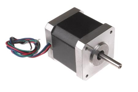
The name of this motor is given so because the rotation of shaft is in step form which is different from DC or any other motor. In other motors the speed of rotation, the stop angle are not in complete control unless necessary circuit is inserted. This non-control is present because moment of inertia, which is simply a character to start and stop on command without delay. Consider a DC motor, once its powered the speed of motor increases slowly until it catches the rated speed.
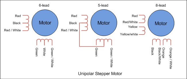
The step motor hybrid does not work on constant supply. It can only be worked on controlled and ordered power pulses. Before going any further we need to talk about UNIPOLAR and BIPOLAR stepper motorS. As shown in figure in a UNIPOLAR stepper motor we can take the center tapping of both the phase windings for a common ground or for a common power. In first case we can take black and white for a common ground or power. In case 2 black is take for a common. In case3 orange black red yellow all come together for a common ground or power.

In BIPOLAR stepper motor we have phase ends and no center taps and so we will have only four terminals. The driving of this type of stepper motor is different and complex and also the driving circuit cannot be easily designed without a microcontroller.
The circuit which we designed here can only be used for stepper motors of UNIPOLAR type.
The power pulsing of UNIPOLAR stepper motor wholesale price will be discussed in circuit explanation.
Circuit Components
+9 to +12 supply voltage
555 IC
1KΩ, 2K2Ω resistors
220KΩ pot or variable resistor
1µF capacitor, 100µF capacitor (not a compulsory, connected in parallel to power)
2N3904 or 2N2222 (no. of pieces depend on type of stepper if it’s a 2 stage we need 2 if it’s a four stage we need four)
1N4007 (no. of diodes is equal to no. of transistors)
CD4017 IC, .
Why do you use a stepper motor?

The name of this motor is given so because the rotation of shaft is in step form which is different from DC or any other motor. In other motors the speed of rotation, the stop angle are not in complete control unless necessary circuit is inserted. This non-control is present because moment of inertia, which is simply a character to start and stop on command without delay. Consider a DC motor, once its powered the speed of motor increases slowly until it catches the rated speed.
The step motor hybrid does not work on constant supply. It can only be worked on controlled and ordered power pulses. Before going any further we need to talk about UNIPOLAR and BIPOLAR stepper motorS. As shown in figure in a UNIPOLAR stepper motor we can take the center tapping of both the phase windings for a common ground or for a common power. In first case we can take black and white for a common ground or power. In case 2 black is take for a common. In case3 orange black red yellow all come together for a common ground or power.

In BIPOLAR stepper motor we have phase ends and no center taps and so we will have only four terminals. The driving of this type of stepper motor is different and complex and also the driving circuit cannot be easily designed without a microcontroller.
The circuit which we designed here can only be used for stepper motors of UNIPOLAR type.
The power pulsing of UNIPOLAR stepper motor wholesale price will be discussed in circuit explanation.
Circuit Components
+9 to +12 supply voltage
555 IC
1KΩ, 2K2Ω resistors
220KΩ pot or variable resistor
1µF capacitor, 100µF capacitor (not a compulsory, connected in parallel to power)
2N3904 or 2N2222 (no. of pieces depend on type of stepper if it’s a 2 stage we need 2 if it’s a four stage we need four)
1N4007 (no. of diodes is equal to no. of transistors)
CD4017 IC, .
Why do you use a stepper motor?
没有评论:
发表评论