2018年12月13日星期四

Analysis of a Hybrid Step Motor - Part One

Hybrid stepper motors wholesale are used as actuators for equipment where position detection accuracy is required, such as the joints of robots or rotary tables for machine tools. The rotor has a construction that sandwiches a magnet that is magnetized in the axial direction between two rotor cores that have serrated teeth to create salient poles, and the tips of the stator core’s teeth are shaped like gears as well. Because the rotation resolution is determined by the number of rotor teeth and the number of phases for the drive coil, the design uses large number of teeth, such as 50 or 100, so the angle resolution can be increased .The most important characteristics for a stepper motor are the controllability, the detent torque, which is a non-excitation holding torque, and the stiffness torque, which is an excitation holding torque, and not the motor’s output.


The two-plated rotor core of a stepper motor has an N pole on one side and an S pole on the other, so a multipole magnet is achieved by deviating the saliency of the gear condition by 1/2 pitch. Consequently, the magnetic circuit is 3D. There are also times when the division pitch geometry of the teeth is complicated, so it is necessary to carry out a 3D electromagnetic field analysis using the finite element method (FEM) to proceed with an accurate preliminary study.


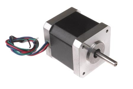
This document introduces how the detent torque and stiffness torque can be calculated for a hybrid nema 34 stepper motor.


The detent torque is shown in fig. 1, and the magnetic flux distribution in the XY-plane at the rotation position of 0.45 degrees is shown in fig. 2. A closer view to show the flux distribution in the gap is shown in fig. 3. These results reveal that the flux in both the rotor and stator is saturated even with no excitation. The flux leakage around the tips of the teeth, due to saturation, can be expected to have a large effect on the detent torque.


Fig. 4 shows the stiffness torque with one-phase excited and fig. 5 shows the stiffness torque with two-phase excited. The flux distribution in the gap of the XY-plane with one-phase excited is shown in fig. 6, and the flux distribution in the gap of the XY-plane with two-phase excited is shown in fig. 7. As with the detent torque, the magnetic flux around the teeth is saturated. The flux leakage caused by the saturation can be expected to also have a large effect on the stiffness torque.

What’s the difference between detent torque and holding torque?


2018年12月8日星期六

How to set a stepping motor’s current limit

 Stepper-motor current limiting serves a few functions. Stepper-motor overcurrent can cause overheating as detailed in FAQ: Aren’t heat and noise common stepper motor problems? At its most extreme, overcurrent can cause rotor demagnetization. Recall that current effects acceleration — as in FAQ: What are the requirements for stepper motor acceleration? So any design that uses microstepping needs current limiting, as different windings require different current levels.

Options for current limiting abound. The simplest to use a resistor. This option is easy to implement but has drawbacks. It causes significant heating and (because factors such as motor inductance change with rotor position and frequently go undocumented) can be difficult to implement.


Another option — linear motor current limiters — employ a pair of power resistors. They offer better performance than simple limiters using a single resistor. Instead of limiting current linearly as resistor circuits, they limit current asymptotically … and usually the limit is far above a motor’s rated current. Both types of current limiters are automatic. However, they generate heat.

Still other methods exist to set current limit as part of open-loop systems.

One is to use a voltage boost at the beginning of startup. The controller delivers almost the entire supply voltage early. At the target current, the voltage drops down to only what’s necessary to maintain target current. Use of a dual-voltage supply is also possible. Here the drive applies high voltage until the current reaches the target level, then it switches to operating voltage and the high voltage switches off.

One caveat: This scheme can pose a problem if the drive applies the high voltage applies too long — as that can risk of burning out the motor or demagnetizing it. If the design uses software control to run this circuit and the programmer is unfamiliar with the application, the software may not prevent this situation.

Pulse-width modulation or chopping is another option. Here as current increases, the controller holds supply input to 100% duty cycle.

At target current, duty cycle drops to whatever is necessary to maintain operation. While effective, this method’s drawback is torque ripple. This can cause high-pitched noise in smaller motors. In larger motors, this can create ac voltages on nearby lines. To reduce ripple, designs will often increase the chopper frequency … but this can only go so far before losses are excessively high.

BASICS OF STEPPER MOTORS YOU SHOLD KNOW

2018年12月5日星期三

Stepper Motor Driver Circuit You Shold Know

Technically stepper motor driver circuit is a Decade Binary Counter circuit. The advantage of this circuit is, it can be used to drive stepper motors having 2-10 steps. Before going any further let’s discuss more about the basics of stepper motor.

Stepper Motor Image
The name of this motor is given so because the rotation of shaft is in step form which is different from DC or any other motor. In other motors the speed of rotation, the stop angle are not in complete control unless necessary circuit is inserted. This non-control is present because moment of inertia, which is simply a character to start and stop on command without delay. Consider a DC motor, once its powered the speed of motor increases slowly until it catches the rated speed.

The step motor hybrid does not work on constant supply. It can only be worked on controlled and ordered power pulses. Before going any further we need to talk about UNIPOLAR and BIPOLAR stepper motorS. As shown in figure in a UNIPOLAR stepper motor we can take the center tapping of both the phase windings for a common ground or for a common power. In first case we can take black and white for a common ground or power. In case 2 black is take for a common. In case3 orange black red yellow all come together for a common ground or power.

Unipolar stepper motor

In BIPOLAR stepper motor we have phase ends and no center taps and so we will have only four terminals. The driving of this type of stepper motor is different and complex and also the driving circuit cannot be easily designed without a microcontroller.

The circuit which we designed here can only be used for stepper motors of UNIPOLAR type.

The power pulsing of UNIPOLAR stepper motor wholesale price will be discussed in circuit explanation.


Circuit Components
+9 to +12 supply voltage
555 IC
1KΩ, 2K2Ω resistors
220KΩ pot or variable resistor
1µF capacitor, 100µF capacitor (not a compulsory, connected in parallel to power)
2N3904 or 2N2222 (no. of pieces depend on type of stepper if it’s a 2 stage we need 2 if it’s a four stage we need four)
1N4007 (no. of diodes is equal to no. of transistors)
CD4017 IC, .

Why do you use a stepper motor?

2018年11月24日星期六

Comparing closed-loop and open-loop stepper systems

Recently, I got the chance to work with Eric Rice and Jeff Kordick at OYOSTEPPER Products on a technical feature detailing new technologies making step motor systems even faster, quieter, and more energy-efficient than ever before.

Step motor systems have come a long way from the early days of voltage drives and full stepping. First came PWM drives and microstepping and then digital signal processors (DSPs) and anti-resonance algorithms. Now, closed-loop stepper designs could become the new cornerstone of the motion control industry. One such closed-loop system implements on an integrated motor design that includes a feedback device, driver and controller boards, power, communication and I/O electronics, and system connectors on the motor’s side and back.

Consider how open-loop stepper systems are simple beasts. One simply sets the drive for the motor’s rated current and the drive will do its best to supply that current to the motor at all times, whether the resulting torque is needed or not. This often causes the generation of heat instead of energy towards the application function — and is the reason why open-loop stepper systems typically run hotter than closed-loop counterparts .


Above is a Relative Comparison Chart for StepSERVO closed-loop systems versus open-loop systems. Note the superior performance of the closed-loop stepper motor system as demonstrated in the results of laboratory testing that compare two systems for acceleration (torque), efficiency (power consumption), position error (accuracy), heat generation, and noise levels.


2018年11月20日星期二

Why to Buy Stepper Drives and Controls at OYOSTEPPER

A stepper motor is an electrically powered motor. Current is passed to the drive shaft, which then rotates in small step-like motions. Stepper motors do not rotate smoothly or continuously. They are designed to power digital devices, which require precise and tightly-controlled motor movements with no feedback. Items containing stepper motors include cars, computers, toys, robotic arms, printers, and robotic model kits.

When purchasing stepper motor drivers, also called controllers, several factors must be taken into consideration. Buyers should make sure that the motor is compatible with the driver, as there are several different types. The number of wires in the motor determines whether a bipolar or unipolar driver is required. Maximum current input and output of the motor also impact which driver to purchase, as do features such as step modes, step frequency, and protection circuitry.

Why to Buy Stepper Drives and Controls at OYOSTEPPER


Buying Stepper Drives and Controls on OYOSTEPEPR

OYOSTEPEPR has a large selection stepper drives and controls, available in both new and used condition, and the price range varies significantly across the range. Buyers should use specific search terms to get the most appropriate results results, such as "micro stepper drive," "chopper drive," or "unipolar chopper drive." Buyers can search from the Business and Industrial, Consumer Electronics, and Computer, Tablets, and Networking portals, which also provide relevant search results.

Buyers can narrow their search results by choosing to view specific listing types, such as Buy It Now or auction format. Other result narrowing options include viewing only new or only used items, items within a specific price range, or only items from Top Rated Sellers.

Buyers should ensure the drive is in good working order, particularly if it is a secondhand unit.

Buyers should also ensure that the postage costs are acceptable, and should take note of the estimated delivery time. They should also determine whether the seller offers postal insurance for expensive items. Buyers are encouraged to contact sellers and ask any questions not covered in the item description.

Buyers should choose to buy from sellers who have large amounts of positive feedback, or sellers who possess a "Top Rated Seller" seal. A "Top Rated Seller" seal indicates that the seller has a sterling eBay reputation, and has provided many customers with quality products and great service.

Conclusion
To choose the correct analog stepper drivers or closed loop stepper driver
 buyers must consider their budget, the intended application of the stepper motor, and the required features. Buyers should ascertain which drives are compatible with the motor in question, since some motors will not work with an incorrect drive. The required features are also important considerations. For example, bi-level drives, while very stable and efficient, are not capable of performing micro stepping. This means that despite their reliability, these drives do not offer the same precision and resolution as a chopper drive. For those on a tight budget, secondhand drives in good working order are a good choice. This enables buyers to purchase a high end drive model at an affordable price.

2018年10月26日星期五

High Torque Nema 11 DC Stepper Motor NEMA 11 Frame Size 28 x 28mm 1.8°Step Angle

NEMA 11 Frame Size(28 x 28mm)
1.8° Step Angle
High Torque - Up to 17 oz-in
High Step Accuracy and Resolution
Low Vibration and Noise
DC Stepper Motor
Can be Customized for
-Winding Current
-Shaft Options
-Cables and Connectors
Typical Applications: Inject printers, Analytical and Medical Instruments, Textile Equipment, Embroidery Machine, Precision Telescope Positioning Systems, High Speed Dome Camera and Robotics
cnc stepper motor/step motor/stepper motor/NEMA 11 28 x 28mm stepping motor
NEMA 11 Frame Size 28 x 28mm 1.8°Step Angle


The 11HS Series DC Stepper Motor have bigger size than Nema 8HS DC Stepper Motor, but have much bigger torque than the latter. These DC Stepper Motor were designed to offer the highest possible torque while minimizing vibration and audible noise. Unlike DC motors, the 11HS series DC Stepper Motor already has a very high torque at low speed and often gears are not required which leads to considerably more economical drive solutions. The standard 4 lead wire DC Stepper Motor can be connected to allow the flexibility for your application. OSM can also customize the winding to perfectly match your voltage, current, and maximum operating speed.

Need help choosing the right Stepper Motor? Read this: Uni-polar vs Bi-polar or learn more about Stepper Motor Basics.

2018年10月8日星期一

Question on Closed loop control on cnc machine

So I saw a video showing rather amazing control of the brushless motors via encoder. Great job on this esc! I'm glad I decided to google 'open source esc' today!

Nema 23 External 66mm Stack 2.5A Lead 2.54mm/0.1" Length 250mm

My question is pretty simple. I made a cnc machine with lead screws and nema 34 closed-loop stepper motors/drivers. They are slow. I'd love to replace them with rc brushless motors and VESC's with encoders for much higher speed milling.

However, my electronics, and most cnc electronics, send out STEP/DIR pulses. DIR is held high or low for forward/backwards, and step is move an increment. Is there a way to read this in VESC or do I need to fashion some kind of adapter board to convert signals?
Nema 34 Stepper Motor External 79mm Stack 3.12A Lead 2.54mm/0.1" Length 150mm

Also, in the video, I never saw what happened if you commanded more then 360 degrees of motion. Is there a value overflow? Or can the degree count keep going up and down and into the negatives or positives forever?

This is the machine, by the way, but I have a feeling that if this works I might try to make my own lower power version of the vesc and make brushless servo motor drives for all of my stepper devices (3d printer, laser cutter, etc) However, annoyingly, I dont seem to have any pictures of the new revision. It no longer uses the big bldc motor as a spindle, it now uses a 3 phase 1.5kw vfd driven water cooled spindle.

2018年9月29日星期六

Specific stepper motor parameters

  1. Step angle – represents angular displacement of the rotor for one control impulse;
Specific stepper motor parameters

  1. Maximum no load start frequency – represents the maximum control impulse frequency at which the unloaded 
  2. Best stepper motor can start, stop or reverse without losing steps;
  3. Limit start frequency – represents the maximum impulse frequency at which the motor can start without losing steps, when a given moment of inertia and torque load are presented at the shaft;
  4. Pull-in torque – represents maximum torque load at the shaft, at which the motor can start without losing steps;
  5. Maximum no load frequency – represents the maximum impulse frequency that the motor can follow without losing synchronization;
  6. Maximum frequency – maximum frequency of impulses at which a motor keeps its timing for given torque load and inertia;
  7. Pull-out torque – maximum torque that can be maintained by the motor at a certain speed, without losing steps;
  8. Angular speed – is calculated as a product between the stepping angle and the control frequency;
  9. Detent torque – represents the value of the holding torque presented by at the motor shaft when it is not electrically energized.
Also read about how to correctly implement different types of control sequences in our dedicated article about stepper motor control.

2018年9月21日星期五

Geared stepper motor to main focuser shaft

This solution is most widely used in commercial focusers. It consists of relatively small stepper motor connected with proper gear box with ratio in the range 1:10 to 1:200. Shaft from the gearbox is connected to main focuser shaft. Backlash is present, as it is intrinsic quality of each mechanical gearbox, but it can be easily compensated with proper settings of focuser driver. This solution is also more expensive than other two, because there is additional cost of gearbox. 
Example stock solutions that are available for this solution:
Drawbacks of this solution are price and backlash. Advantages are: low power consumption, no power required when idle, compact size, high resolution and compatibility with many commercial solutions (Robofocus, Moonlite, USB Focus, Pegasus Astro, AstroLink and other). 
Custom ATM adaptation of stepper motor with planetary gearbox to main focuser shaft. Aluminium shaft coupler is visible in the picture between motor and focuser.

Stepper motor to microfocuser shaft

This is quite easy solution that requires low power stepper motor, because torque to move microfocuser shaft is pretty low. All you need to do is to find suitable stepper motor for 9-12V. It can be both unipolar or bipolar motor, and it needs to provide torque at level 2-3 Ncm or more. Motor shaft needs to be connected to microfocusing shaft using a shaft coupler with proper diameter. 
Example motors that will work for this solution:
  • Nema 8 geared Bipolar 1.8deg 0.3A 12V 3Ncm motor
  • Nema 14 geared Bipolar 1.8deg 0.4A 12V 14Ncm motor
  • Nema 14 geared Bipolar 1.8deg 0.4A 10V 5Ncm motor
  • Round Nema 14 geared Bipolar 0.9deg 0.5A 8.5V 5Ncm motor
  • Nema 16 geared Bipolar 1.8deg 0.4A 12V 21Ncm motor 
  • Nema 17 geared  motor Bipolar 1.8deg 0.3A 12V 16Ncm
This kind of connections is quite simple and inexpensive. The drawbacks of this solutions are: microfocusing knob is not available anymore for manual focusing (however you can use shaft coupler to rotate it manually), and when microfocusing gear is not adjusted well, there can be some slip at its mechanism.
Stepper motor coupled with microfocusing shaft. No additional gearbox is required.

2018年9月10日星期一

Advantages of Electric Linear Actuators

Reduced downtime. Electric linear actuators (whether screw- or belt-driven) are very low-maintenance. Regreasing may be the only regular maintenance necessary, and many screw-driven models are lubricated for the life of the actuator.


Electric actuators commonly use stepper motors or brushless DC (BLDC) servo motors to generate torque. Because both motors are brushless, there is no contact between the rotor and stator other than the load bearings. This eliminates motor maintenance, and allows the motor life to equal the life of the bearings.

A stepper motor may run at 100 percent of its rated current during a motion, and have a substantial steadystate holding current as well. This holding current can waste energy because it locks the rotor to a position regardless of whether any work is being performed. However, many stepper drivers can reduce the current to minimal levels.


Electric step motor linear actuators can meet these demands because they offer more control over position, speed, and force. High-resolution feedback devices are common today and easily allow for micrometer-scale precision. Advanced drive tuning can compensate for things like changing loads, inertia, and preventing mechanical resonance. Electric actuator manufacturers often provide sizing software to accurately size an electric actuator to the application, and select a motor with enough torque to reach the desired speeds.


2018年9月4日星期二

THE STEPPER MOTOR CONTROLLER YOU CHOOSE MATTERS!

Equally the stepper motor controller that you use will have a major impact on the mechanical performance you are able to achieve using the motor. If the controller is not able to deliver more power than the motor can handle then it is unlikely that you will be able to achieve the maximum possible mechanical performance from the motor.

As an example of this, our stepper motors with integrated controllers have higher powered controllers the bigger the motors get.

See the table below for an overview of frame sizes.


WHAT NEXT?
If your interest in motor sizes was purely academic then we hope we have helped. If you have any questions about this please do not hesitate to get in touch and we will do our best to help.

Alternatively if you are looking for a motor and aren’t sure which is best for your application then you could start by having a quick look at our standard range.

We offer a range of stepper motors of different sizes which are available in geared or standard format.

As always, if you have any questions about choosing the right motor or the pros and cons of a long stack NEMA 17 versus a short stack NEMA 23 MOTOR(for example) then you can get in touch with us via online chat, phone or email.

2018年9月3日星期一

A Small and Llight Gearbox for a Stepper Motor

I wanted to build a small and light gearbox for a stepper motor (used as excuse: for building a light extruder for a 3D printer - didn't trust the bowden setup, and the scavenged driver might not have enough torque for a direct drive - real cause: playing around with the lasercutter :-)

DIY PLANETARY GEARBOX FOR NEMA17 STEPPER MOTOR


I decided to use POM (polyoxymethylen), since it's quite strong, self lubricant and you can cut it with a lasercutter... if you have a good ventilation: Burning POM produces formaldehyde, not the best product for your health. So using a CNC mill might be more healthy.

On the other hand, we have now a three stage filtering system especially for formaldhyde, and a just fine tuned laser cutter - perfect for fine teeth.

I used apart from the laser cutter:

- POM (i used three different thicknesses, 2,3 and 4mm to get a really small and light version, but using only one (4mm) thickness is also possible)

- 3* bearings 3mm inner diameter, 7mm outer diameter, 3mm height

- 1* bearing 5mm inner diameter, 10mm outer diameter, 4mm height

- 3* 3mm hexagon socket head screw 12mm long, with 12 washer and 3 nuts

- 1* 5mm hexagon socket head screw 30mm long (but trimmed down) and 3 nuts (small height)

- 2* 3mm hexgon socket head screw 40mm long with 2 washers

- NEMA17 stepper driver (5mm diameter axis)

- MK8 drivegear for 5mm axis


2018年8月20日星期一

JVL QuickStep closed-loop integrated stepper motors

They do this with greater efficiency and less motor heating because motor phase currents are regulated up and down according to need. Performance of the closed-loop steppers are similar to servo motors, but with higher torque and often without need of gearboxes, reducing costs.

JVL QuickStep closed-loop integrated stepper motors


Oyostepper is a true closed-loop control system that compensates step angle errors during a movement and correct errors within a full step. If load becomes too high speed is lowered and position errors will always stay within two full-steps. Smart digital design and very high update rates (36 MHz) means there is no need of any manual adjustment or setup. It works like a perfect stepper motor benefiting from the servo motor technology. Advantages compared to open loop steppers include position feedback and control, fast and easy commissioning with no tuning needed, no stalling or step losses, faster positioning and more cycles per second and more. Advantages over servo motors include very high torque at low speed, often three to four times higher in the same motor flange size; very high ratio of inertia, often up to 40:1; faster commissioning, with no tuning needed, same price as open loop steppers and total stiffness at standstill, with full holding torque.

See more:
https://www.playbuzz.com/item/243ef9d0-b027-49ef-bc83-9354d49f451f

2018年8月16日星期四

Spectrum External Motor Planetary Gear Motor

For the DIY'r, these gear stepper motors allow you to drive a dolly or other custom motion control accessory through the M3/M4  ports on the side of your spectrum.


The 14:1 Motor has:
  Efficient stepper motor planetary gear Drive
  8 mm mounting shaft
The Direct Drive Motor has:
 5 mm mounting shaft

Both Motors have a short lead spectrum connector with strain relief. This allows you to plug into the AUX port of the spectrum with no soldering or crimping.

Extension cables are not included and are needed.

Motor Speed

14:1: Strong enough to do video and timelapse moves up slopes and vertical. Slower motor.
Direct Drive: Our fastest motor and what we pair to the shark slider for interviews. Great for all horizontal moves and turbo mode.

ADVANTAGES OF A CLOSED-LOOP STEPPING MOTOR SYSTEM

2018年8月10日星期五

How to make 5-Axis CNC Machining

Whether you’re sculpting a masterpiece from marble or milling a blisk from titanium, the basic principle is the same: start with a block of material and remove the unnecessary bits until the target object is all that’s left. Of course, the details of that process are much more complicated, especially for 5-axis machining.


What is 5-axis CNC Machining?
In the simplest terms, 5-axis machining involves using a CNC to move a part or cutting tool along five different axes simultaneously. This enables the machining of very complex parts, which is why 5-axis is especially popular for aerospace applications.

However, several factors have contributed to the wider adoption of 5-axis machining. These include:

A push toward single-setup machining (sometimes referred to as “Done-in-One”) to reduce lead time and increase efficiency
The ability to avoid collision with the tool holder by tilting the cutting tool or the table, which also allows better access to part geometry
Improved tool life and cycle time as a result of tilting the tool/table to maintain optimum cutting position and constant chip load.

What are the Axes in 5-Axis?
We all know the story about Newton and the apple, but there’s a similarly apocryphal story about the mathematician and philosopher, Rene Descartes.

Descartes was lying in bed (as mathematicians and philosophers are wont to do) when he noticed a fly buzzing around his room. He realized that he could describe the fly’s position in the room’s three-dimensional space using just three numbers, represented by the variables X, Y and Z.
This is the Cartesian Coordinate system, and it’s still in use more than three centuries after Descartes’ death. So X, Y and Z cover three of the five axes in 5-axis machining.

What about the other two?
Imagine zooming in on Descartes’ fly in mid-flight. Instead of only describing its position as a point in three-dimensional space, we can describe its orientation. As it turns, picture the fly rolling in the same way a plane banks. Its roll is described by the fourth axis, A: the rotational axis around X. (1 axis cnc kit  or mini 4 axis cnc kit)


(Image courtesy of Hurco North America.)

2018年8月8日星期三

Design of Controlling System for Linear Stepper Motor Based on DSP2407

into linear micro-step motion directly. In condition of open-loop, it can provide accurate and reliable straight-line displacement, velocity and acceleration control, and it can be used to constitute an open-loop system without feedback. However, due to its structural characteristics, there were some shortcomings as follows [1-2]:

(1) It can not automatic accelerate and decelerate smoothly as DC motor and AC motor, out-of-step or blockage will appear probably in circumstance of high speed and large variation.

(2) Its Whirling speed is not steady enough, step angle is overlarge, especially, and concussion phenomenon will appear occasionally.
Focus on shortcomings of linear step motor, this paper carry out two optimization for the application of its driver: control the process of acceleration and deceleration when speed (pulse frequency) of system fluctuate largely; Providing subdivision function for the system, which can promote positional accuracy and steady degree at lower speed; Theoretical analysis and experimental results show that system’s dynamic and static performance has been improved noticeably by optimization design.


2 Control System Configuration
As the core of the system control unit TMS320LF2407A was used to achieve a signal generating.TMS320LF2407A was a powerful general-purpose I/O port and PWM
336 H. Zheng and W. Cui output function, it can output a 16-way PWM waveform. PWM frequency change can be realized stepper motor speed and position control [4-5].

Control signal was used to set up the linear stepper motor operation mode and software integration of the motor control the start and stop, the positive/negative
circumrotate, acceleration/deceleration and location and orientation. Display circuit with real-time display in the operation of the motor speed, and other parameters. The system schematic was shown as Figure 1.
Design of Controlling System for Linear Stepper Motor Based on DSP2407


3 Acceleration/ Deceleration Control Arithmetic hybrid stepper motor started from a low frequency, run at high speed after the uniform. When approaching of another terminal location, the stepper motor run slowdown, and then it could accurately stop in the terminal position. Starting vibration and mechanical impact of route end is restrained effectively. The process can be a variety of variable speed control mode time curve.

Line acceleration/deceleration control Curve was shown as Figure 2 (a). Plans in the segment AB, BC, CD, were on behalf of acceleration, uniform and deceleration. The
letter ‘N’ was behalf of line


2018年6月7日星期四

Which Has Higher Stopping Accuracy - Stepper Motor or Servo Motor?

Customer Inquiry: Looking for a motor with good stopping accuracy. How much of a difference is there between stepper motors and servo motors?

Assumption: The AC servo motor NX Series is equipped with a 20-bit encoder, thus it should have a fine resolution, and good stopping accuracy.

First, it is necessary to clarify the difference between resolution and stopping accuracy: Resolution is the number of steps per revolution and it is also called a step angle for stepping motors. It is needed when considering how precise the required positioning needs to be. Stopping accuracy is the difference between the actual stop position and theoretical stop position.

Stepper Motor vs Servo Resolution and Stopping Accuracy

Does this mean that the AC servo motor equipped with a high accuracy encoder has better stopping accuracy than hybrid step motor?

Not quite. In the past there was no issue with the concept of "stopping accuracy of servo motors being equal to encoder resolution within ±1 pulse." However, recent servo motors are equipped with the 20 bit encoder (1,048,576 steps) which has a very fine resolution. Because of this, errors due to the encoder installation accuracy have a huge effect on stopping accuracy. Therefore, the concept of stopping accuracy has slightly started to change.

Source:
http://obd2newsfrance.blogspot.com/2018/06/basics-of-stepper-motors-you-should-know.html

2018年5月5日星期六

Some differences between bipolar and unipolar stepper motor

A bipolar stepper motor for sale has one winding per stator phase. A two phase bipolar stepper motor will have 4 leads. In a bipolar stepper we don’t have a common lead like in a uni-polar stepper motor. Hence, there is no natural reversal of current direction through the winding.

A bipolar stepper motor has easy wiring arrangement but its operation is little complex. In order to drive a bipolar stepper, we need a driver IC with an internal H bridge circuit. This is because, in order to reverse the polarity of stator poles, the current needs to be reversed. This can only be done through a H bridge.

Some differences between bipolar and unipolar stepper motor

Bipolar Stepper Drives
Many companies have started assembling their own bipolar stepper drives. Care must be taken that you connect the stepper motor correctly to the drive. Also the drive must be able to supply sufficient current for you stepper. The micro-controller must only provide the step and direction signal to the drive. This method will occupy only two micro-controller pins and is very helpful in projects that require large number of micro-controller pins for other functions.


Unipolar Stepper v/s Bipolar Stepper
Both bipolar steppers and unipolar stepepr motor for sale are used widely in projects. However, they have their own advantages and disadvantages from the application point of view. The advantage of a uni-polar motor is that we do not have to use a complex H bridge circuitry to control the stepper motor. Only a simple driver like ULN2003A will do the task satisfactorily. But, there is one disadvantage of uni-polar motors. The torque generated by them is quite less. This is because the current is flowing only through the half the winding. Hence they are used in low torque applications. On the other hand, bipolar stepper motors are a little complex to wire as we have to use a current reversing H bridge driver IC like an L293D. But the advantage is that the current will flow through the full coil. The resulting torque generated by the motor is larger as compared to a uni-polar motor.

Source:https://www.oyostepper.com/article-1076-Some-differences-between-bipolar-and-unipolar-stepper-motor.html

2018年4月27日星期五

Are you searching for the best electronic equipment at a reasonable rate?

Are you searching for the best electronic equipment at a reasonable rate? Great! Do you know the right type of equipment to get started? If no, need not worry! Web shopping portals feel delighted to get you introduced to some exclusive collections. Rather than hovering to and fro, you may get the best within a few clicks at the comfort of your home.

Online shopping has now become a common trend due to numerous benefits in the association. Buying the best BLDC Motor is preferable due to a large range of collections along with justified price and ease. These equipment are a bit costly due to which purchasing them from reliable online dealers will give you the best output.

36V 4000RPM 0.44Nm 184W 7.3A Ф57x109mm 57BLR High Speed Brushless DC Motor

Cost Along with Size – Vital Point to Take into Consideration

Cost along with size and functionality are some of the vital things that need to be looked at the time of making an online purchase of electronic gadgets. In case you are searching for something great comprising of numerous functionalities, then you need to pay a bit high and vice versa. The one available with little functionalities may be availed at rock bottom price list. 

Better to go through online classified sites to get into touch with numerous and variable types of items. There is also a possibility that you may get in touch with great deals which will really prove to be highly beneficial. Next comes the turn of size! The selection of size must be done by a number of people for whom you will be cooking. 

Why Decide the Size in a Precise Manner?

People prefer going with motors belonging to gigantic sizes. Also, medium-sized motors have gained high popularity. Functionality is another vital thing that needs to be kept into high consideration. Some of the features that need to be looked after include the following:
  • Easy repairing
  • Availability of parts
  • Efficiency
  • Flexibility

Better to conduct an online survey to get to know more about the same in detail. There are numerous tips by experts that have been aired for the convenience of users. You need to ensure that these tips along with functionalities may be into usage in actual usage rather than sounding soothing. Such vital pieces of information will let you make the right type of selection.

Purchasing of an Optical Encoder from a Reliable Supplier

Whether online or offline, it is recommended to shake hands with a reliable supplier to make the best use of your hard earned investment. If you are planning to purchase the most suitable stepper motor with encoder
, then you must approach the most trustworthy supplier. You may get in touch with a trustworthy supplier online by:
  • Visiting the World Wide Web in a thorough manner
  • Going through reviews that have been posted by previous clients
  • Getting in touch personally with the supplier

The supplier hesitant to open up all details in a broad manner must be abandoned completely. Following these vital tips will let you get in touch with the right type o item online without any difficulty.

2018年4月20日星期五

TWO DIMENSIONS OF Linear Stepper Motor

We’ve all heard linear motors, like those propelling Maglev trains, described as “unrolled” versions of regular electric motors. The analogy is apt and helps to understand how a linear motor works, but it begs the question: what if we could unroll the stator in two dimensions instead of just one?


That’s the idea behind [1.8 deg stepper motor] two-axis stepper motor, which looks like it has a lot of potential for some interesting applications. Build details are sparse, but from what we can gather from the videos and the Hackaday.io post, [BetaChecker] has created a platen of 288 hand-wound copper coils, each of which can be selectively controlled through a large number of L293 H-bridge chips and an Arduino Mega. A variety of sleds, each with neodymium magnets in the base, can be applied to the platen, and depending on how the coils are energized, the sled can move in either dimension. For vertical applications, it looks like some coils are used to hold the sled to the platen while others are used to propel it. There are RGB LEDs inside the bore of each coil, although their function beyond zazzle is unclear.

We’d love more details to gauge where this is going, but with better resolution, something like this could make a great 3D-printer bed. If one-dimensional movement is enough for you, though, check out this linear stepper motor for sale that works on a similar principle.

2018年4月13日星期五

Stepper Motor Control by Varying Clock Pulses

Stepper motor online control circuit is a simple and low-cost circuit, mainly used in low power applications. The circuit is shown in figure, which consist 555 timers IC as stable multi-vibrator. The frequency is calculated by using below given relationship:

types of stepper motors


Frequency = 1/T = 1.45/(RA + 2RB)C Where RA = RB = R2 = R3 = 4.7 kilo-ohm and C = C2 = 100 µF.

The output of timer is used as clock for two 7474 dual ‘D’ flip-flops (U4 and U3) configured as a ring counter. When power is initially switched on, only the first flip-flop is set (i.e. Q output at pin 5 of U3 will be at logic ‘1’) and the other three flip-flops are reset (i.e. output of Q is at logic 0). On receipt of a clock pulse, the logic ‘1’ output of the first flip-flop gets shifted to the second flip-flop (pin 9 of U3). Thus logic 1 output keeps shifting in a circular manner with every clock pulse. Q outputs of all the four flip-flops are amplified by Darling-ton transistor arrays inside ULN2003 (U2) and connected to the stepper motor windings orange ,brown, yellow, black to 16, 15 ,14, 13 of ULN2003 and the red to +ve supply.

The common point of the winding is connected to +12V DC supply, which is also connected to pin 9 of ULN2003. The color code used for the windings is may vary form make to make. When the power is switched on, the control signal connected to SET pin of the first flip-flop and CLR pins of the other three flip-flops goes active ‘low’ (because of the power-on-reset circuit formed by R1-C1 combination) to set the first flip-flop and reset the remaining three flip-flops. On reset, Q1 of IC3 goes ‘high’ while all other Q outputs go ‘low’. External reset can be activated by pressing the reset switch. By pressing the reset switch, you can stop the stepper motor. The motor again starts rotating in the same direction by releasing the reset switch.

Now you have got an idea about the types of super high torque stepper motor
 and its applications if you have any queries on this topic or on the electrical and electronic projects leave the comments below.

2018年4月3日星期二

Three Major Types of Stepper Motor

Three types of stepper motors are in common use today: Permanent magnet, variable reluctance, and hybrid. Of these, hybrid steppers are by far the most popular – they combine the high points of the other two designs using multi-toothed stator poles and a permanent magnet rotor.

No matter the type of stepper motor including nema 17 stepper motor, engineers should be familiar with the three step modes:

Three Major Types of Stepper Motor

Full Step
With 200 total rotor teeth, full step mode is the equivalent of a 1.8-degree full step angle. When the motor is operating as intended, one digital pulse from the device’s driver is equal to one step. Typically, both windings are energized while the current is reversed alternately.

Half Step
In half step mode, the motor rotates at a full 400 steps per revolution. The step angle is .9 degrees, half the amount of full step. This is ideal for producing smoother motion at the expense of a noticeable, though not severe, reduction in torque.

Microstep
A relatively new innovation, microstep mode can subdivide a complete step into 256 microstep. This means a complete revolution is an astonishing 51,200 steps—enhancing positional accuracy and smoothness over a wider variety of speeds.

Stepper Motors 101: How Do They Work?

2018年3月21日星期三

Construction of Hybrid Stepper Motor

The stator of this stepper motor is same as its permanent magnet or reluctance type counterpart. The stator coils are wound on alternate poles. In this, the coils of different phases are wound on each pole, usually two coils at a pole which is referred as a bifilar connection.

The rotor consists of a permanent magnet which is magnetized in axial direction to create a pair of magnetic poles (N and S poles).  Each pole is covered with uniformly spaced teeth. The teeth are made up of soft steel and two section, of which on each pole are misaligned each other by a half-tooth pitch.

Working of Hybrid Stepper Motor:

Working of Hybrid Stepper Motor


This motor works similar to that of permanent magnet stepper motor. The figure above shows 2-phase, 4-pole, 6-tooth rotor hybrid stepper motor. When the phase A-A’ is excited with a DC supply, keeping B-B’ unexcited, the rotor aligns such that the south pole of the rotor faces north pole of the stator while north pole of rotor faces south pole of the stator.

Now, if the phase B-B’ is excited, keeping A-A’ switched off in such a way that upper pole becomes north and lower becomes south, then the rotor will align to a new position by moving through counterclockwise direction. If the phase B-B’ is oppositely excited such that the upper pole becomes south and lower becomes north, then the rotor will turn clockwise direction.

By a proper sequence of pulses to the stator, the motor will turn in desired direction. For every excitation, rotor will get locked into new position, and even if excitation is removed motor still maintains its locked condition due to the permanent magnet excitation. The step angle of this 2-phase, 4-pole, 6-tooth rotor motor is given as 360/ (2 × 6) = 30 degrees. In practice, hybrid motors are constructed with more number of rotor poles in order to get high angular resolution.


2018年3月20日星期二

Stepper Motor Advantages and Disadvantages

Stepper Motor Basics
"A stepper motor is an electromechanical device which converts electrical pulses into discrete mechanical movements. The shaft or spindle of a stepper motor rotates in discrete step increments when electrical command pulses are applied to it in the proper sequence. The motors rotation has several direct relationships to these applied input pulses. The sequence of the applied pulses is directly related to the direction of motor shafts rotation. The speed of the motor shafts rotation is directly related to the frequency of the input pulses and the length of rotation is directly related to the number of input pulses applied."

This is a topic about the Stepper Motor Basics, after read this artical, you will know basic informations about stepper motor.

Stepper Motor Advantages and Disadvantages

Advantages:

1. The rotation angle of the motor is proportional to the input pulse.

2. The motor has full torque at standstill (if the windings are energized)

3. Precise positioning and repeatability of movement since good stepper motors have an accuracy of 3 – 5% of a step and this error is non cumulative from one step to the next.

4. Excellent response to starting/stopping/reversing.

5. Very reliable since there are no contact brushes in the motor. Therefore the life of the motor is simply dependant on the life of the bearing.

6. The motors response to digital input pulses provides open-loop control, making the motor simpler and less costly to control.

7. It is possible to achieve very low speed synchronous rotation with a load that is directly coupled to the shaft.

8. A wide range of rotational speeds can be realized as the speed is proportional to the frequency of the input pulses.

Disadvantages:

1.    Resonances can occur if not properly controlled.
2.    Not easy to operate at extremely high speeds.

The motors that are included in a motor home may be different than a stepper motor but the general dynamics are the same. Those who are looking for a motor home for sale should be especially wary of the condition of the motor, though you can always go to an RV dump site to look for spare parts.

Source:https://www.oyostepper.com/article-1071-Stepper-Motor-Advantages-and-Disadvantages.html