into linear micro-step motion directly. In condition of open-loop, it can provide accurate and reliable straight-line displacement, velocity and acceleration control, and it can be used to constitute an open-loop system without feedback. However, due to its structural characteristics, there were some shortcomings as follows [1-2]:
(1) It can not automatic accelerate and decelerate smoothly as DC motor and AC motor, out-of-step or blockage will appear probably in circumstance of high speed and large variation.
(2) Its Whirling speed is not steady enough, step angle is overlarge, especially, and concussion phenomenon will appear occasionally.
Focus on shortcomings of linear step motor, this paper carry out two optimization for the application of its driver: control the process of acceleration and deceleration when speed (pulse frequency) of system fluctuate largely; Providing subdivision function for the system, which can promote positional accuracy and steady degree at lower speed; Theoretical analysis and experimental results show that system’s dynamic and static performance has been improved noticeably by optimization design.
2 Control System Configuration
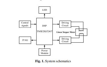
As the core of the system control unit TMS320LF2407A was used to achieve a signal generating.TMS320LF2407A was a powerful general-purpose I/O port and PWM
336 H. Zheng and W. Cui output function, it can output a 16-way PWM waveform. PWM frequency change can be realized stepper motor speed and position control [4-5].
Control signal was used to set up the linear stepper motor operation mode and software integration of the motor control the start and stop, the positive/negative
circumrotate, acceleration/deceleration and location and orientation. Display circuit with real-time display in the operation of the motor speed, and other parameters. The system schematic was shown as Figure 1.
3 Acceleration/ Deceleration Control Arithmetic hybrid stepper motor started from a low frequency, run at high speed after the uniform. When approaching of another terminal location, the stepper motor run slowdown, and then it could accurately stop in the terminal position. Starting vibration and mechanical impact of route end is restrained effectively. The process can be a variety of variable speed control mode time curve.
Line acceleration/deceleration control Curve was shown as Figure 2 (a). Plans in the segment AB, BC, CD, were on behalf of acceleration, uniform and deceleration. The
letter ‘N’ was behalf of line

没有评论:
发表评论